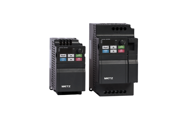
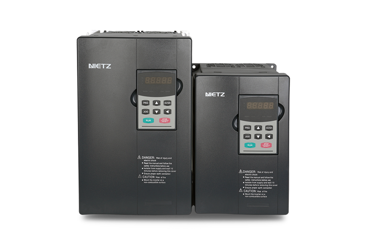
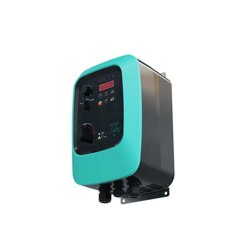
APV Pro IP65/IP55 AC Drives
APV Pro series is a high protection class AC Drive IP65/55. Integrated Power Switch on/off, potentiometer, forward/reverse knob
|
|

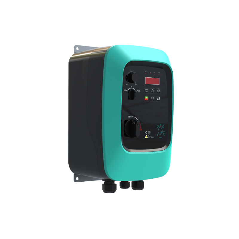
APV Pro series is a high protection class AC Drive IP65/55. Integrated Power Switch on/off, potentiometer, forward/reverse knob
|
|
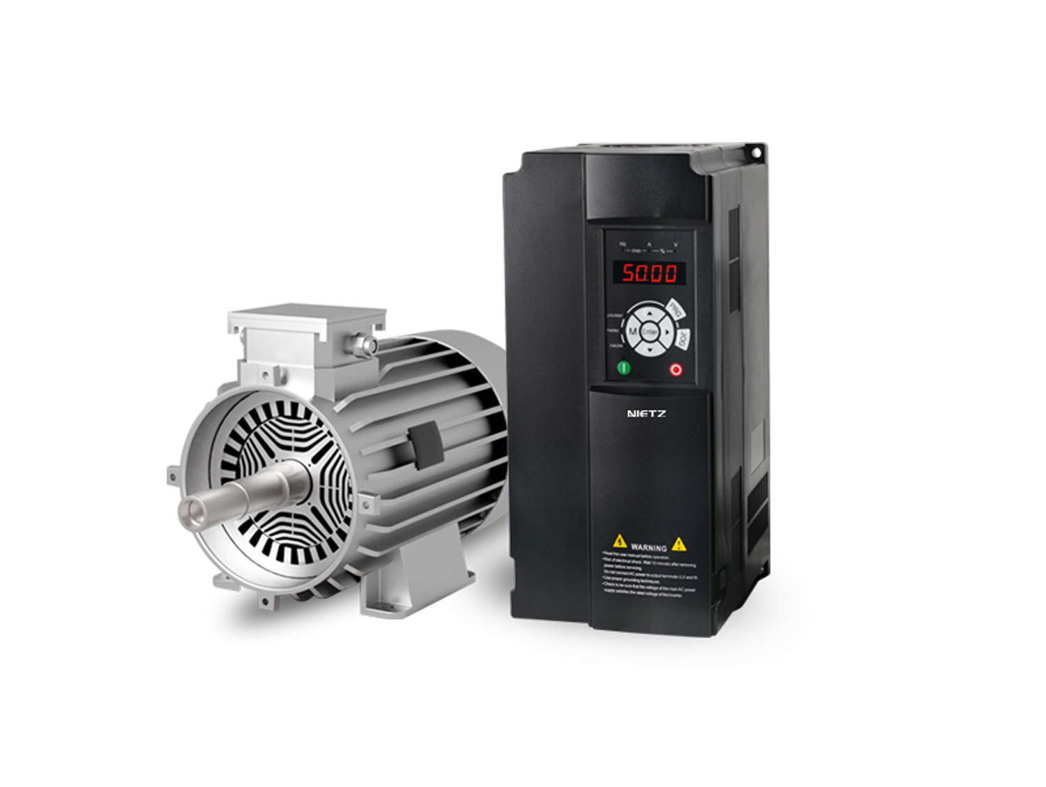
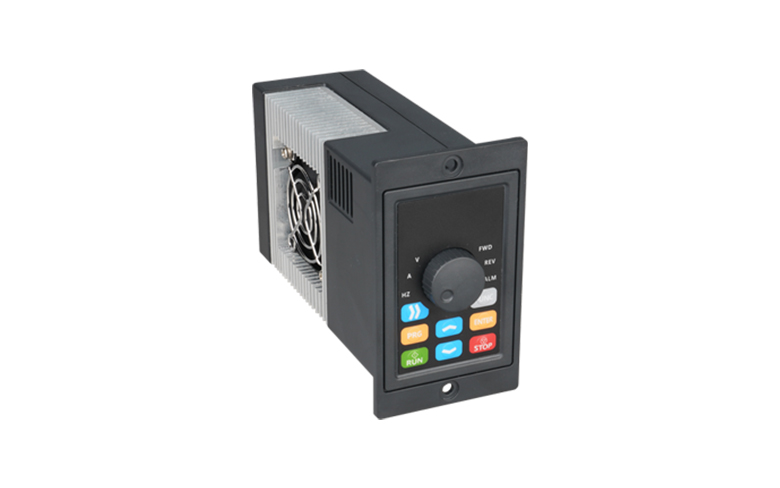
APV Pro Motor-mounted variable frequency drives
220V~480V Voltage; V/F/Vector control type
Controls AC Motor, PM Motor (expansion card ABZ encoder)
IP66 protection class.
Motor-mounted variable frequency drives design. Compact structure; Easy to set, wiring and mount, save space, cost and time.
Integrated design eliminates concerns about interference and leakage current from long output cables, saving installation costs.
Built-in PID algorithm enables direct variable frequency constant voltage control and water shortage protection.
Equipped knob of forward/reverse; potentiometer; power switch on/off on control panel. Easy to installation, wiring, and operation.
Multiple start-up modes (terminal switch, communication, power-on auto-start, configurable via parameters)
Comprehensive protection functions (short circuit, phase loss, undervoltage, overvoltage, overload, overcurrent, overheating)
Built-in EMC filter Class C; STO (Safe Torque Off) function
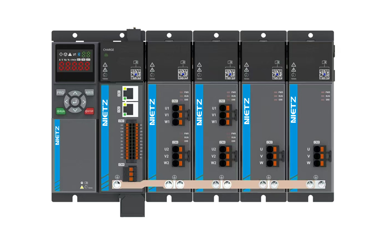
Various cummuniction method: Modbus RS485 standard; Expansion cards Profibus, ASI, EtherCAT, Profinet are avaliable.
Such expasion cards as DI/DO, AI/AO, relay output .
● Fan, pumps, conveyors, Mixers
● Food processing Machinery, transmission mechnical
● Wood tools Equipments and etc